Let me start by setting up this post like I’m talking to someone who might be scrolling through our website at 9 a.m., mid-way through prepping a bill of materials for their power supply design, or maybe troubleshooting a noise issue that’s been bugging their team for weeks. A few weeks back, I hopped on a call with an engineer at a mid-sized solar inverter manufacturer, and he was frustrated—he’d swapped three different filter inductors in two days, and none of them were hitting their noise targets. The big question he kept circling back to wasn’t “what’s an inductor” or “why do we need it”—it was, “How do I get the power rating right, so I don’t waste more time or money?” That’s the exact question we’re breaking down today. Filter Inductor
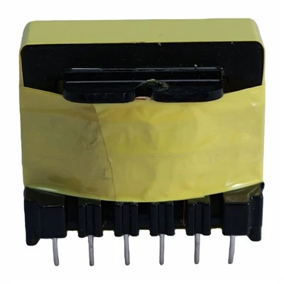
First, let’s make sure we’re speaking the same language, because power rating for a filter inductor isn’t a single number you pull out of a datasheet and plug into a design. It’s a balance of two big, often competing, factors: continuous current handling and thermal stability. I see so many engineers grab a part that lists a “5A rating” and call it good, only to have that inductor overheat after 10 minutes of full load. Why? Because that 5A rating might mean the part hits 40°C above ambient at that current, which might be fine for a portable device but deadly for a commercial inverter that’s rated for 20 years of 50°C ambient operation.
Let’s dive into continuous current first, because that’s the most common starting point for anyone calculating power rating. Filter inductors are used in almost every power conversion circuit—DC-DC converters, inverters, PFC stages, even automotive on-board chargers—their job is to smooth out current ripples, right? The ripple current flows through the inductor along with the main DC (or AC) load current. The key here is that the core of an inductor has a saturation point. Saturation is when the core material can’t hold any more magnetic flux, so the inductance drops off sharply. If your current spikes high enough to push the core into saturation, the inductor stops filtering properly—those ripples come roaring back, which can damage semiconductors, create electromagnetic interference (EMI), and kill efficiency.
So, how do you calculate the DC bias current that will get you close to saturation? That’s where the datasheet’s “rated current” (sometimes called “saturation current”) comes in. Most datasheets will list two common current ratings: one for saturation, and one for heating. The saturation current is usually the current that causes a 10% drop in inductance from the nominal value. That’s a hard line—you should never run your filter inductor anywhere near that, unless you’re okay with losing filter performance. For example, if your design’s maximum load current is 10A, and the inductor’s saturation current is 12A, that’s a start, but it’s not enough for power rating yet.
Now the second part: thermal current. That’s the current that causes the inductor’s core and windings to heat up to an acceptable temperature rise. Every inductor has resistance in its copper windings, and core loss from the changing magnetic field. When current flows through those windings, it generates I²R loss, which turns into heat. Core loss is proportional to the square of the ripple frequency and the flux density in the core—so higher frequencies mean higher core loss, especially for ferrite cores, which are super common for filter inductors. The thermal current is the current that results in a specific temperature rise, usually 40°C or 65°C above ambient. Most datasheets label this as the “rated current” for power handling, because it tells you how much current you can run continuously without overheating.
Here’s where so many designs go wrong: they pick a saturation current that’s just above their peak load, but that might line up with a thermal current that’s too low. Let’s take that example from the solar inverter engineer I mentioned earlier. His peak load current was 15A, so he grabbed an inductor with a 16A saturation current—great, he thought, that avoids saturation. But when he ran it, the inductor’s temperature hit 90°C above ambient in 15 minutes. That’s because the thermal current for that inductor was only 13A at his operating frequency, not 16A. The datasheet had both numbers, but he’d skipped reading the fine print about which current corresponded to which rating. That’s the mistake we see all the time—don’t just scan for the highest current number, figure out which one applies to your application.
Let’s break down the variables that change the power rating beyond just current, because a filter inductor’s power rating isn’t one-size-fits-all. First, operating temperature. If your equipment is going to sit in a 40°C ambient in Arizona, you can’t use a thermal current rating tested at 25°C. Core materials lose permeability at higher temperatures, and copper resistance goes up too—by about 0.4% per °C. That means at 50°C ambient, your allowable temperature rise is lower (since total inductor temperature = ambient + rise, and you don’t want to go over the core’s temperature limit, which is usually around 120°C for standard ferrites). So if you need the total temperature to stay under 100°C, your temperature rise can only be 50°C at 50°C ambient, not 65°C. That knocks your effective power rating down a fair bit.
Next, frequency. Filter inductors for high-frequency applications (like automotive OBCs running at 100kHz, or server power supplies at 500kHz) have way higher core loss than low-frequency parts for industrial motors at 50/60Hz. Let’s say you have two identical inductors: one rated for 10A at 50Hz, and another rated for 8A at 100kHz. The power rating drops because the core is generating more heat from the fast-changing magnetic field. That’s why, when you’re sourcing a filter inductor, you have to give your supplier the operating frequency, not just the load current—we can’t adjust the core design without that detail.
And ripple current, yes, we touched on this, but it’s critical. Ripple current adds to the RMS current in the inductor, not just the peak. Wait, hold on—peak current is what causes saturation, but RMS current is what causes heating, because I²R loss is based on the root mean square. So if your load current is 10A DC, and your ripple current is 2A peak-to-peak, your RMS current is sqrt((10²) + (2²/12)) = ~10.02A. That’s barely higher, but if your ripple is 5A peak-to-peak at 100kHz, your RMS is ~10.52A, and the core loss from that ripple adds a lot of extra heat. If you ignore ripple when calculating power rating, you’ll end up with a hotter inductor than you planned for.
Now, how do we at our company work through this with customers, because this isn’t just textbook stuff—this is what we do for every order. We don’t just send a datasheet and say “pick the 15A part.” First, we ask for three things: maximum load current, operating frequency, and maximum allowable inductor temperature rise. For the solar inverter engineer, that meant he wasn’t just giving us 15A—he needed 15A at 20kHz, with a max temperature rise of 50°C at 50°C ambient. We pulled our inductor library, cross-referenced core sizes, winding counts, and tested parts to match his requirements. We also run thermal simulations in-house now, which is a game-changer—we can predict how a part will perform at his exact operating conditions before we even build a prototype.
Wait, let’s address a common myth I hear all the time: “Bigger inductor = higher power rating.” That’s mostly true, but not always. A larger core can handle more current before saturation, and has more surface area to dissipate heat, so it can run higher RMS currents. But if you oversize too much, you’re wasting money and taking up space on the PCB, which is a big deal for automotive and consumer devices. We once had a customer who ordered a 20A inductor for a 12A load, just because he thought bigger was better. When he got the part, it was twice the size and cost 30% more, even though a 13A part would have fit his needs perfectly. The moral here is: match the power rating to your application, don’t overbuild unless you have to.
Another myth: “Power rating is fixed for a given inductor.” No, it adjusts based on how you use it. If you only run your solar inverter at 50% load, that 15A inductor can handle more than 15A continuously, because it’s not generating as much heat. Conversely, if you run it at 100% load in a 60°C ambient, that same 15A inductor might only be good for 12A, because the temperature rise will be too high. That’s why we always advise customers to look at the derating curves in the datasheet, or work with our team to adjust ratings for their specific operating conditions.
Let’s also talk about what happens when you get the power rating wrong, because that’s the cost of getting it right. If you underrate the power, you get overheating, which shortens the inductor’s lifespan—core materials can crack or degrade when exposed to high temperatures over time, and windings can get damaged. That leads to field failures, which are way more expensive than sourcing the right part the first time. We had a customer in telecom who went with an underrated inductor for a base station power supply, and ended up with a 20% failure rate in the first year, costing them thousands in on-site repairs. If they’d worked with us to size the inductor correctly upfront, that wouldn’t have happened.
If you overrate, you’re spending unnecessary money and taking up valuable PCB space. For a compact EV charger, every square millimeter counts, so an oversized inductor can add grams of weight and cost extra, without any benefit to performance. We work with all kinds of customers—from startups designing wearables to large aerospace manufacturers—and our goal is always to find the sweet spot where the inductor meets the power requirements, fits their design, and stays within their budget.
So, putting this all together, what’s the actual process for figuring out the power rating of your filter inductor? Let’s outline it step by step: first, calculate your peak load current to avoid saturation—leave a 10-20% safety margin here, because component tolerances and unexpected load spikes are common. Second, calculate your RMS current, including both DC load current and the RMS of the ripple current, to account for heating. Third, note your operating frequency and ambient temperature, because both change how much loss the inductor generates. Fourth, look for datasheets that list both saturation current (for peak) and thermal current (for RMS), and make sure those numbers are tested at conditions close to yours. Fifth, if you’re not sure, reach out to a supplier who can run simulations or prototype parts for you—don’t guess, because guesswork leads to mistakes.
I know this sounds like a lot of numbers and fine print, but it’s worth getting right. The power rating of a filter inductor isn’t just a specification—it’s a critical factor in how well your entire power system performs, how long it lasts, and how much it costs to build.
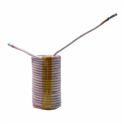
If you’re in the middle of a design right now, stuck on sizing the right filter inductor, or you’ve dealt with failed parts from mis-matched power ratings, our team can help. We work with customers across industries to design filter inductors that fit their exact power, frequency, and space requirements, no guesswork, no overpriced overbuilding, no more headaches from field failures. If you have a project you’re working on, just get in touch with our sales engineering team to talk through your needs—we’ll walk through the calculations with you, send prototype parts for testing, and make sure the inductor you get is exactly what you need.
Current Transformer References:
- Mohan, N., Undeland, T. M., & Robbins, W. P. (2003). Power Electronics: Converters, Applications, and Design (3rd ed.). John Wiley & Sons.
- Elmen, G. W. (1936). Magnetic Materials of High Permeability for Electrical Circuits. Bell System Technical Journal.
- Ferrite Core Manufacturer Association. (2021). Standard Test Methods for Power Inductor Current Ratings. International Electrotechnical Commission (IEC) 61308.
- Automotive Engineering Council. (2022). Power Inductor Design Guidelines for Electric Vehicle On-Board Chargers. SAE International.
Dongguan Hensiron Electric Co., Ltd.
As one of the most professional filter inductor suppliers in China, we have world-leading production equipment and strong manufacturing capabilities. Please feel free to buy high quality filter inductor made in China here from our factory. Customized orders are welcome.
Address: Building 4, Xinxing Industrial Zone, Wangao Road, Wanjiang Street, Dongguan City, China
E-mail: jessica@dghensiron.com
WebSite: https://www.dghensiron.com/
